RPICT7V1 v2.0: Difference between revisions
No edit summary |
|||
| Line 2: | Line 2: | ||
RPICT7V1 version 2.0 | RPICT7V1 version 2.0 | ||
[[File: | [[File: IMG_0980_small.png | right]] | ||
This is the new version of the RPICT7V1. It now features the same microcontroller as an Arduino UNO. | This is the new version of the RPICT7V1. It now features the same microcontroller as an Arduino UNO. | ||
The best of all is the possibility to stack up to 5 boards together to increase the sensor capacity onto one single raspberrypi. | The best of all is the possibility to stack up to 5 boards together to increase the sensor capacity onto one single raspberrypi. | ||
Revision as of 17:34, 16 November 2016
RPICT7V1 version 2.0

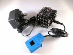
This is the new version of the RPICT7V1. It now features the same microcontroller as an Arduino UNO. The best of all is the possibility to stack up to 5 boards together to increase the sensor capacity onto one single raspberrypi.
- 7 AC current sensors.
- 1 AC Voltage sensor.
- Compute real power.
- Fit on Raspberrypi 4 holes mounting pattern.
- AtMega328 Mcu (Arduino UNO)
- MCP3208 ADC
- Stackable (5 boards together)

Recommended sensors
- AC Current sensor: SCT-013-000
- AC Voltage sensor:
- UK: 77DB-06-09
- EU: 77DE-06-09
- US: 77DA-10-09
Stacking Configuration
5 boards can be stacked together to offer up to 35 SCT sensors capacity on one Raspberrypi.
In the stacked configuration only one board has a Microcontroller which is the Master board. For the slave board the microcontroller should be removed.
Jumpers
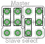
There are four jumpers to configure the board as Master or Slave. The 5 possible configurations are:
| Type | Master | Slave 1 | Slave 2 | Slave 3 | Slave 4 |
|---|---|---|---|---|---|
| CS Pin | 10 | 6 | 7 | 8 | 9 |
| Jumpers | 
|

|

|

|

|
Modifying the sketch
The sketch must be adapted to read sensors from the slave. It contains two functions to declare and configure sensors.
ct1.current(<adc_pin>, <cs_pin>)
and
ct1.voltage(<adc_pin>, <cs_pin>)
adc_pin is the pin number of the analog to digital converter on the selected board. It should be 2,3,4,5,6,7,8 for current and 1 for voltage.
cs_pin is the chip select pin number. This is used to select the board we are interested in. See jumper table above. It should be 6,7,8,9 for slave1234 and 10 for the master board.
For example to define ct1 with voltage and current from board slave2 on 3rd SCT the declarations should be as follow:
ct1.current(3, 7);
ct1.voltage(1, 7);
Mixing declarations between two boards is also possible. For example using voltage of master board and current on 3rd sensor slave2:
ct1.current(3, 7);
ct1.voltage(1, 10);
Files
Emoncms Config
For default sketch. Used as single board only (not stacked).
 [[11]]
   nodename = my_RPICT7V1
   firmware = v1.2
   hardware = RPICT7V1
   [[[rx]]]
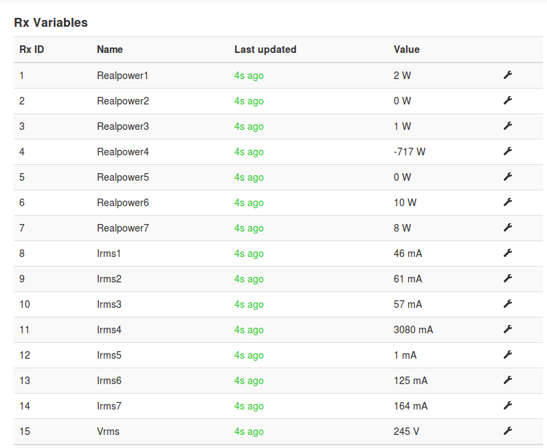
      names = Realpower1, Realpower2, Realpower3, Realpower4, Realpower5, Realpower6, Realpower7,Irms1, Irms2, Irms3, Irms4,Irms5,Irms6,Irms7,Vrms
      datacode = h
      scales = 1,1,1,1,1,1,1,1,1,1,1,1,1,1,1
      units =W,W,W,W,W,W,W,mA,mA,mA,mA,mA,mA,mA,V
Sketch Upload
In order to program the board an avr programmer with 6pin SPI connector is needed.
In Arduino IDE select board as Arduino Uno. Upload sketch using File | Upload Using Programmer.
An ARduino UNO board can be used to program the chip. The micontroller should be removed from the RPICT7V1 board and fitted on the Uno to allow programming.


