Stepper control generic: Difference between revisions
| Line 55: | Line 55: | ||
The board has provision for an i2c port. This can be used to connect to some external device (lcd screen, slave device). Or it can be connected to another arduino board to serve as slave device. | The board has provision for an i2c port. This can be used to connect to some external device (lcd screen, slave device). Or it can be connected to another arduino board to serve as slave device. | ||
The recommended library for use of the i2c is TinyWireM from this link here which has been modified for attiny84 chips. | The recommended library for use of the i2c is TinyWireM from this link here which has been modified for attiny84 chips. | ||
[[Use a LCD i2c with attiny84]] | [[Use a LCD i2c with attiny84]] | ||
[[Stepper Control Board with LCD]] | |||
===Serial Port=== | ===Serial Port=== | ||
Revision as of 13:13, 26 April 2015
Arduino Stepper Control Board - Any Driver
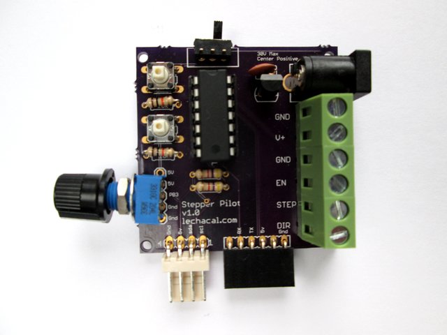
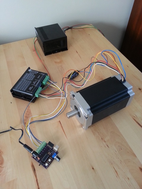
The tiny stepper controller is a controller board for stepper motor. It can be controlled manually (potentiometer and switches) and programmed with Arduiono IDE.
Technical Specifications
Stepper Motor driver board: A4988
Microcontroller: Attiny84.
Input Power: 12Volts. (30V max)
Power Socket: 2.1mm Jack. Center positive.
Motor connector: 4 way molex.
Manual Control ready with:
- Potentiometer for speed.
- Push button for single step increment.
- Slider switch for direction selection.
- i2c port
- Serial port in FTDI configuration
Hardware Controls
Slide Switch
The slide switch can be used as control - generally used for direction control. It is connected to digital input 3 on the arduino chip. Direction pin to the driver is connected to digital output 1.
#define Switch 3
#define Direction 1
Push Buttons
Two push buttons are available. These can be used for any desired manual function such as speed up, move left, start, stop etc...
They are configured with digital input 0 and 2.
#define Button1 2
#define Button2 0
Potentiometer
The board host a potentiometer for variable control such as speed. It is connected to analogue input 3.
#define Pot 3
i2c port
The board has provision for an i2c port. This can be used to connect to some external device (lcd screen, slave device). Or it can be connected to another arduino board to serve as slave device. The recommended library for use of the i2c is TinyWireM from this link here which has been modified for attiny84 chips. Use a LCD i2c with attiny84 Stepper Control Board with LCD
Serial Port
The serial connector as a FTDI layout to allow connecting directly a FTDI adaptor. This will allow communication from the board to a computer. e.g. sending commands to the board or displaying debug information.
Sketch Examples
Default Sketch
The default sketch loaded in the Attiny84 is a basic sketch to control the motor manually. The potentiometer will be use as speed control.
A demonstration can be seen on this video
i2c Control
The two i2c pins of the Attiny84 are available on the board to be controlled from an i2c master.
This is a sketch for the Attiny85 for speed and direction control. Commands are as follow
"a" for direction 1 - e.g. Master will issue Wire.write("a")
"b" for direction 2 - e.g. Master will issue Wire.write("b")
"delay:" for speed control - e.g. Master will issue Wire.write("1500:")
":" for stopping the motor - e.g. Master will issue Wire.write(":")
Delay must be a number followed by a ":" which is the stop character. This number is the delay in microseconds between each steps.
Download Slave i2c Sketch.
Download Master i2c Sketch.


