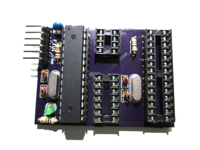
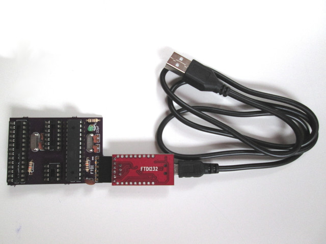
FTDI Programmer
This is a programmer board for use with a FTDI adaptor. This board connects to a computer a FTDI/USB adaptor.
Technical Specifications
Currently known supported Micro Controller Units:
Attiny85
Attiny45
Attiny13
Attiny84
Atmega328
Atmega168
Atmega8
Operate on 5Volts.
Firmware
The firmware used by the programmer is the sketch provided by the Arduino Example sketch ArduinoISP. See File | Examples | ArduinoISP.
Usage
Connect the hardware
Insert the MCU to program on the programmer board. Beware of the direction when the inserting the MCU. The small dot must be pointed toward the left of the board (opposite the leds).
Connect the Programmer board to the FTDI adaptor. Both grounds must be connected together.
Connect the FTDI adaptor to the computer with a USB cable.
Make sure the FTDI adaptor is set to operate on 5V.
Once all connected the Programmer board will show heartbeat with the green led.
Upload Bootloader
If programming an arduino MCU for the first time you must burn the bootloader onto it. For this first select the appropriate board in the Arduino IDE. Tools | Board . For example ATtiny85 @ 8Mhz or Arduino UNO. Then select Tools | Burn Bootloarder.
Upload Sketch (ATtiny)
Open your sketch file with the Arduino IDE. Make sure you select the appropriate MCU type in Tools | Board. Upload the sketch from the IDE.
Upload Sketch (ATmega)
It is possible to use this board to upload a sketch to an ATmega chip. The primary ATmega chip form the board must be removed and replaced with the chip that you wish to program. Open your sketch file with the Arduino IDE. Make sure you select the Arduino UNO type in Tools | Board. Upload the sketch from the IDE.

