RPICT3T1: Difference between revisions
| (31 intermediate revisions by the same user not shown) | |||
| Line 1: | Line 1: | ||
[[File: | [[File:IMG_0537_small.png | 300px | right]] | ||
[[File:IMG_0533_small.png | 300px | right]] | |||
[http://lechacalshop.com/gb/rpict-series/26-raspberrypi-1x-current-sensor-adaptor-1-voltage-emoncms.html Link to shop] | [http://lechacalshop.com/gb/rpict-series/26-raspberrypi-1x-current-sensor-adaptor-1-voltage-emoncms.html Link to shop] | ||
| Line 5: | Line 6: | ||
This page is for board specific information. More information can be found on the [[Raspberrypi_Current_and_Temperature_Sensor_Adaptor | generic page for RPICT series]]. | This page is for board specific information. More information can be found on the [[Raspberrypi_Current_and_Temperature_Sensor_Adaptor | generic page for RPICT series]]. | ||
=Overview= | Information shown here also applies for [[RPIZ_CT3T1]] and [[RPICT3T1_RLY2]]. | ||
==Overview== | |||
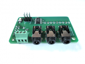
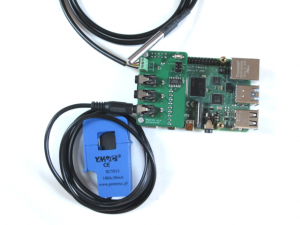
The RPICT3T1 measures AC Power and Temperature. | The RPICT3T1 measures AC Power and Temperature. | ||
| Line 13: | Line 16: | ||
* Attiny84 Microcontroller | * Attiny84 Microcontroller | ||
=Notice= | ==Notice== | ||
Power is computed using a fixed estimated Voltage. This estimated voltage can be configured. Default value is 240V. You will be able to change this to 110 or | Power is computed using a fixed estimated Voltage. This estimated voltage can be configured. Default value is 240V. You will be able to change this to 110 or 230 depending on the country where it is used. | ||
If you require more accurate power measurement then use the [[RPICT3V1]] board instead. This will also read Voltage and calculate Real Power. A voltage sensor will be required in this case. | If you require more accurate power measurement then use the [[RPICT3V1]] board instead. This will also read Voltage and calculate Real Power. A voltage sensor will be required in this case. | ||
=Compatibility= | ==Compatibility== | ||
[[File:IMG_0535_small.png | 300px | right]] | |||
{| class="wikitable" | {| class="wikitable" | ||
|+ | |+ | ||
| Line 41: | Line 45: | ||
|Yes | |Yes | ||
|- | |- | ||
|Raspberrypi 4 B | |||
|Yes | |||
|- | |||
| Raspberrypi Zero | |||
| Use [[RPIZ_CT3T1]] instead | |||
|} | |} | ||
* Asus Tinkerboard has been reported to work with RPICT units. Note we wont be able to provide support for the Tinkerboard. | |||
==Recommended sensors== | ==Recommended sensors== | ||
| Line 48: | Line 60: | ||
** SCT-019 | ** SCT-019 | ||
** SCT-006 | ** SCT-006 | ||
** SCT-024 400A/100mA | |||
** SCT-031 600A/100mA | |||
==Temperature Sensor== | ==Temperature Sensor== | ||
| Line 59: | Line 73: | ||
[[File:IMG_1176_small.png | 200px]] | [[File:IMG_1176_small.png | 200px]] | ||
Using the latest sketch 3.3 up to 8 temperature sensors can be connected. | |||
See also the DS18B20 Junction Board for sale [http://lechacalshop.com/gb/internetofthing/80-ds18b20-junction-board.html here]. | |||
[[File:IMG_0108_small.png | 300px |link=http://lechacalshop.com/gb/internetofthing/80-ds18b20-junction-board.html]] | |||
==Configuration== | ==Configuration== | ||
| Line 67: | Line 87: | ||
[[Attiny Over Serial Configuration A2 | Configuration over serial for sketch version 3.0]]. | [[Attiny Over Serial Configuration A2 | Configuration over serial for sketch version 3.0]]. | ||
==Calibration== | ==Calibration== | ||
| Line 75: | Line 92: | ||
If calibration is required only ICAL has any effect on the calibration. | If calibration is required only ICAL has any effect on the calibration. | ||
VCAL and PHASECAL might be present in the config but have no effect. These should be ignored. | VCAL and PHASECAL might be present in the config but have no effect. These should be ignored for the RPICT3T1. | ||
==Default Data Output== | |||
Using the manufacture firmware the data output is: | |||
NodeID P1 P2 P3 Temperature | |||
P1 P2 P3 in Watt. | |||
Temperature in Celsius. | |||
P1 being the estimated Power using CT1. `Estimated Power` computes power multiplying Irms by Vest. Where Vest is the estimated Voltage setup in the config. By default Vest=240V we recommend to change this to 220V or 110V if your local voltage supply differ. | |||
If you prefer having current in Amperes rather than Power in Watt set VEST=1 in the configuration. In the same manner you can set VEST=1000 to get milliAmperes. | |||
==Emoncms Config (Emonhub)== | ==Emoncms Config (Emonhub)== | ||
| Line 91: | Line 120: | ||
units = W,W,W,C | units = W,W,W,C | ||
=Python demo script= | ==Python demo script== | ||
First of all make sure you have python-serial package installed | First of all make sure you have python-serial package installed | ||
| Line 99: | Line 128: | ||
Then copy the following into an executable file and run it. | Then copy the following into an executable file and run it. | ||
<syntaxhighlight lang="python"> | |||
#!/usr/bin/python2 | #!/usr/bin/python2 | ||
import serial | import serial | ||
| Line 128: | Line 158: | ||
</syntaxhighlight> | |||
==Files== | ==Files== | ||
Please verify which board version is yours. This is written on the circuit board itself. | Please verify which board version is yours. This is written on the circuit board itself. | ||
===Hardware Version 1.3=== | ===Hardware Version 1.3=== | ||
[[File: | [[File:IMG_0536_small.png | 300px | right]] | ||
[http://www.lechacal.com/RPICT/CT3T1/RPICT3T1_v1_3.ino Default Sketch v1.3]<br> | [http://www.lechacal.com/RPICT/CT3T1/RPICT3T1_v1_3.ino Default Sketch v1.3]<br> | ||
[http://www.lechacal.com/RPICT/CT3T1/RPICT3T1_v1_4.ino Default Sketch v1.4] | [http://www.lechacal.com/RPICT/CT3T1/RPICT3T1_v1_4.ino Default Sketch v1.4] | ||
===Hardware Version 2.1=== | ===Hardware Version 2.1=== | ||
[http://www.lechacal.com/RPICT/CT3T1/RPICT3T1_v3.1.ino Default Sketch v3.1]<br> | [http://www.lechacal.com/RPICT/CT3T1/RPICT3T1_v3.1.ino Default Sketch v3.1]<br> | ||
[http://www.lechacal.com/RPICT/CT3T1/RPICT3T1_v3.2.ino Default Sketch v3.2]<br> | |||
[http://www.lechacal.com/RPICT/CT3T1/RPICT3T1_v3.3.ino Default Sketch v3.3] → current default for sold units.<br> | |||
==CAD Drawing== | ==CAD Drawing== | ||
[[File:Rpict3t1_drawing_01.png]] | [[File:Rpict3t1_drawing_01.png | 300px]] | ||
==Related Pages== | ==Related Pages== | ||
Revision as of 12:15, 13 January 2021


This page is for board specific information. More information can be found on the generic page for RPICT series.
Information shown here also applies for RPIZ_CT3T1 and RPICT3T1_RLY2.
Overview
The RPICT3T1 measures AC Power and Temperature.
- 3x AC current sensor
- 1x DS18B20 Temperature Sensor
- Attiny84 Microcontroller
Notice
Power is computed using a fixed estimated Voltage. This estimated voltage can be configured. Default value is 240V. You will be able to change this to 110 or 230 depending on the country where it is used.
If you require more accurate power measurement then use the RPICT3V1 board instead. This will also read Voltage and calculate Real Power. A voltage sensor will be required in this case.
Compatibility

| Version | Compatible? |
|---|---|
| Raspberrypi 1 A | Yes |
| Raspberrypi 1 B+ | Yes |
| Raspberrypi 2 B | Yes |
| Raspberrypi 3 B | Yes |
| Raspberrypi 3 B+ | Yes |
| Raspberrypi 4 B | Yes |
| Raspberrypi Zero | Use RPIZ_CT3T1 instead |
- Asus Tinkerboard has been reported to work with RPICT units. Note we wont be able to provide support for the Tinkerboard.
Recommended sensors
- AC Current sensor:
- SCT-013-000
- SCT-019
- SCT-006
- SCT-024 400A/100mA
- SCT-031 600A/100mA
Temperature Sensor
The DS18B20 temperature sensor can be connected directly to the screw terminal connector.
Connection is as follow:
Vcc - Red
Din - Yellow
Gnd - Black
Using the latest sketch 3.3 up to 8 temperature sensors can be connected.
See also the DS18B20 Junction Board for sale here.
Configuration
See general instructions for
Configuration over serial for sketch version 1.2 1.3 & 2.0.
Configuration over serial for sketch version 3.0.
Calibration
If calibration is required only ICAL has any effect on the calibration.
VCAL and PHASECAL might be present in the config but have no effect. These should be ignored for the RPICT3T1.
Default Data Output
Using the manufacture firmware the data output is:
NodeID P1 P2 P3 Temperature
P1 P2 P3 in Watt. Temperature in Celsius. P1 being the estimated Power using CT1. `Estimated Power` computes power multiplying Irms by Vest. Where Vest is the estimated Voltage setup in the config. By default Vest=240V we recommend to change this to 220V or 110V if your local voltage supply differ.
If you prefer having current in Amperes rather than Power in Watt set VEST=1 in the configuration. In the same manner you can set VEST=1000 to get milliAmperes.
Emoncms Config (Emonhub)
For default configuration. Used as single board only (not stacked).
 [[11]]
   nodename = RPICT1T1
   firmware = RPICT3T1_V1_1.ino
   hardware = RPICT3T1
   [[[rx]]]
       names = Power1,Power2,Power3,Temperature
       datacode = 0
       scales = 1,1,1,1
       units = W,W,W,C
Python demo script
First of all make sure you have python-serial package installed
$ sudo apt-get install python-serial
Then copy the following into an executable file and run it.
 #!/usr/bin/python2
 import serial
 ser = serial.Serial('/dev/ttyAMA0', 38400)

 try:
        while 1:
             # Read one line from the serial buffer
             line = ser.readline()

             # Remove the trailing carriage return line feed
             line = line[:-2]

             # Create an array of the data
             Z = line.split(' ')

             # Print it nicely
             print ("----------")
             for i in range(len(Z)):
                 if i==0:
                     print ("NodeID: %s" % Z[0])
                 elif i in [1,2,3]:
                     print ("Power %d: %s W" % (i, Z[i]))
                 elif i==4:
                     print ("Temperature: %s C" % (Z[i]))

 except KeyboardInterrupt:
        ser.close()
Files
Please verify which board version is yours. This is written on the circuit board itself.
Hardware Version 1.3

Default Sketch v1.3
Default Sketch v1.4
Hardware Version 2.1
Default Sketch v3.1
Default Sketch v3.2
Default Sketch v3.3 → current default for sold units.


