RPICT Fundamentals: Difference between revisions
| Line 91: | Line 91: | ||
===Apparent Power=== | ===Apparent Power=== | ||
Apparent is noted S and is just the product of Irms and Vrms. | |||
[[File:Screenshot_2021-01-16_22-48-09.png]] | |||
===More about it=== | ===More about it=== | ||
[https://en.wikipedia.org/wiki/AC_power#Active,_reactive,_and_apparent_power] | [https://en.wikipedia.org/wiki/AC_power#Active,_reactive,_and_apparent_power] | ||
https://en.wikipedia.org/wiki/Root_mean_square | https://en.wikipedia.org/wiki/Root_mean_square | ||
Revision as of 22:48, 16 January 2021
We will cover some of the basic fundamentals used by the RPICT series below.
Signal Flow
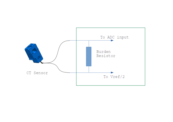
Each signal whether if it's a current or voltage line is first conditioned to obtain the desired range. We perform this either by simply adjusting the burden resistor or by fitting voltage divider or amplifier. This is an important step to condition the sensor range to the ADC range. Sensors may output anything but the ADC requires an input between 0 and Vref*.
The ADC converts a physical analogue signal into something a computer can process. This is where the conversion from real world to digital word happens.
The microcontroller collect raw data from the ADC and computes values such as RMS RealPower PowerFactor etc. It also send the final computation to the Raspberrypi using serial Uart. Note that on some RPICT the ADC is part of the microcontroller.
\* For what follows we sometimes refer to Vref/2. Vref is a reference voltage given to the ADC defining its range. Depending on the type of boards this is either 3.3V or 4.096V. As AC signals are waveform (positive and negative) the signal must be centred on half the range which is Vref/2.
Signal Conditioning
Current
Burden Resistor
Most RPICT series CT range are adjusted using the burden resistor. It is connected directly to the ADC and Vref/2.
The burden resistor can be calculated with the formulae below.
R = (Vref * Nturns) / (2√2 * Irms)
R: Burden resistor value in Ohm
Vref: ADC max voltage range
Nturns: Number of CT sensor turns (see specs).
Irms: Max current to be read in Ampere (rms)
More about this here .
This page has a table with all resistor values for each CT sensor.
The case for RPICT7V1 RPICT8 RPICT4V3 Version 4
RPICT7V1 RPICT8 RPICT4V3 Version 4 are a special design that incorporate an amplifier between the burden resistor and the ADC. These have a much higher cost due to the complexity of components involved.
Refer to this page for the components table information.
Voltage
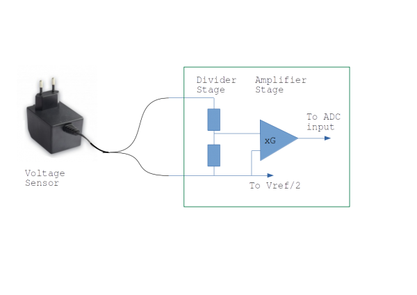
The voltage line has both a divider and an amplifier.
When using a ac/ac adaptor the amplifier gain is set to 1 and the divider is used to reduced the signal amplitude.
When using the ZMPT module the divider ratio is set to 1 (a plain wire) and the amplifier is used to raise the signal level.
Computed Values
RPICT boards mainly read 2 types of waveform. One is current and the other is voltage. Each of them have an instantaneous value at a given time k. Respectively I[k] and V[k].
We will only consider these signals in the discrete time domain as this is how they are exploited by the ADC. Hence k being the iterative time sample.
Instantaneous values I[k] and V[k] are rarely used as they are and it is commonly adopted to use their Root Mean Square (RMS) value instead. You might have heard your country to run on 230V or 120V. These are RMS values.
RMS Signal
Given that the ADC access directly instantaneous values such as I[k] and V[k] the RMS value is given by these formulas below.
N being the number of sample acquired by the ADC. The microcontroller perform these computation using the RPICTlib library.
Estimated Power
Some application that do not use a voltage sensor can have an estimate of the power used by only using Irms. For this the user has to provide Vest which is an estimated value for the voltage. Vest would be either 230V or 120V usually.
This is not calculated in RPICTlib but usually done within the Arduino sketch once Irms has been computed.
Real Power
This is also called Active Power. Technically we compute the average Real Power using the formulae below. Note it requires the use of instantaneous values of I and V like the RMS calculation. Nevertheless this is not a RMS but an average of instantaneous power over time.
RPICTlib does this computation internally.
Apparent Power
Apparent is noted S and is just the product of Irms and Vrms.


