RPICT Stacking Version 5: Difference between revisions
No edit summary |
|||
| Line 57: | Line 57: | ||
The ID of the slave board is selected by means of a jumper link. There are 4 possible slave ID possible. 1 2 3 or 4. See S1 S2 S3 S4 marking on the PCB. | The ID of the slave board is selected by means of a jumper link. There are 4 possible slave ID possible. 1 2 3 or 4. See S1 S2 S3 S4 marking on the PCB. | ||
==Software Configuration== | |||
The RPICT boards do not configure automatically after being stacked. The user must configure this using the tools provided. | |||
The master board can be configured over serial. | |||
The documentation for serial configuration can be found on this page. <br> | |||
[[Over Serial Configuration - Sketch 2.6 | Over Serial Configuration - Sketch 2.6 & 2.7.1]]<br> | |||
[[Over Serial Configuration - Sketch 2.8]]<br> | |||
[[Over Serial Configuration - Sketch 3.0]]<br> | |||
[[File:Online_config_01.png | 300px| link=http://lechacal.com/wiki/index.php/RPICT_Online_Config_Generator]] Starting from sketch 2.4 the board can be configured with the [[RPICT_Online_Config_Generator | online configurator]]. | |||
Revision as of 21:02, 28 September 2020
Page under construction.
This page is for version 5 units. For older versions please refer to this page [RPICT_Stacking | here].
RPICT7V1 RPICT4V3 and RPICT8 version 5 boards can be stacked with an additional slave board. Up to 4 slaves can be stacked on top of a master board. Increasing the number of CT capacity to up to 40.
Version 3 users. Read this -> Version 5 stacking differ from version 3. One individual board can no longer be converted from master to slave or slave to master. Each board is setup as master or slave by design.

Stacking offers the ability to compute Current/Voltage pairs between different board type. For example one might stack 1 RPICT7V1 with 1 RPICT8 and compute Active Power against V1 on RPICT7V1 and all other 15 CT channels on both RPICT7V1 and RPICT8.
RPICT board Stacking
The rpict board concerned by this topic are
RPICT7V1 Slave and RPICT4V3 Slave have not been created yet. Please contact us if you have an interest in them.

Software Limitations
The default sketch limits the number of CV pairs to 28. This allows at least 3 units to be stacked together.
If higher stack are required use the noOSC sketch instead to increase the number of CV pairs to compute.
Slave Board Setup
For now we only provide one slave board type which is the RPICT8 Slave. (We are open to get the RPICT7V1 and RPICT4V3 slave out if we get enough interest).
At purchase time there are 2 types of slave board one can get. Slave 1&3 and Slave 2&4. The main difference between the 2 is the position of the stacking connector.
Slave 1&3

This one can only be stacked on a the master board or a Slave 2&4.
A typical 2 board setup would involve one master and a slave 1&3.
Slave 2&4

This one can only be stacked on top of a Slave 1&3.
Unsoldered
There is also the option to acquire the slave board with stacking connector unsoldered. This allows for deciding the position of the board in the stack at a later stage. Connectors are provided unsoldered with the board.
Jumper Setup
The ID of the slave board is selected by means of a jumper link. There are 4 possible slave ID possible. 1 2 3 or 4. See S1 S2 S3 S4 marking on the PCB.
Software Configuration
The RPICT boards do not configure automatically after being stacked. The user must configure this using the tools provided.
The master board can be configured over serial.
The documentation for serial configuration can be found on this page.
Over Serial Configuration - Sketch 2.6 & 2.7.1
Over Serial Configuration - Sketch 2.8
Over Serial Configuration - Sketch 3.0
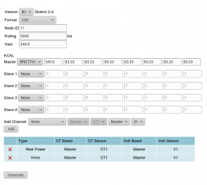 Starting from sketch 2.4 the board can be configured with the online configurator.