RPIZCT4V3T2: Difference between revisions
| (54 intermediate revisions by the same user not shown) | |||
| Line 1: | Line 1: | ||
[[File:Link_to_the_shop.png | link=http://lechacalshop.com/gb/internetofthing/79-rpizct4v3t2.html ]] | |||
[[File: | |||
[[File:IMG_0083_small.png | right | 500px]] | [[File:IMG_0083_small.png | right | 500px]] | ||
=Overview= | ==Overview== | ||
The RPIZCT4V3T2 can be configured to read both single phase and 3 phase systems. | The RPIZCT4V3T2 can be configured to read both single phase and 3 phase systems. | ||
| Line 20: | Line 16: | ||
An enclosure solution is proposed using aluminium extruded case. | An enclosure solution is proposed using aluminium extruded case. | ||
=Specifications= | <span style="color:red">RTD MODULES ARE NO LONGER SOLD - The board will be provided without RTD support. We have dropped the development for these.</span> | ||
==Specifications== | |||
==cpu== | ==cpu== | ||
| Line 37: | Line 35: | ||
* Option to stack mezzanine board for additional sensors. | * Option to stack mezzanine board for additional sensors. | ||
=Recommended sensors= | ==Recommended sensors== | ||
* AC Current sensor: | * AC Current sensor: | ||
** SCT-013-000 | ** SCT-013-000 | ||
| Line 46: | Line 44: | ||
** EU: 77DE-06-09 | ** EU: 77DE-06-09 | ||
** US: 77DA-10-09 | ** US: 77DA-10-09 | ||
** [[ | ** [[ZMPT101B_Module_1x_v2 | ZMPT101B]] | ||
* Temperature: | * Temperature: | ||
** DS18B20 | ** DS18B20 | ||
| Line 53: | Line 51: | ||
** PT1000 (modification required) | ** PT1000 (modification required) | ||
=Temperature Sensor= | ==Temperature Sensor== | ||
===DS18B20=== | ===DS18B20=== | ||
| Line 59: | Line 57: | ||
The temperature port supports mutiple sensor on the same Onewire line. | The temperature port supports mutiple sensor on the same Onewire line. | ||
The sketch is programmed to search for all connected probe at bootup and output all their values when polled | The sketch is programmed to search for all connected probe at bootup and output all their values when polled. | ||
Multiple probes should connected as shown below. | Multiple probes should connected as shown below. | ||
[[File:Ds18b20_daisychain.png | 400px]] | [[File:Ds18b20_daisychain.png | 400px]] | ||
When a new probe is connected the arduino mcu must be restarted for the new probe to be registered. You can reset the Arduino chip with the command below: | |||
lcl-rpict-config.py -a | |||
To connect multiple probe together we suggest the use of our [http://lechacalshop.com/gb/internetofthing/80-ds18b20-junction-board.html DS18B20 junction board]. | |||
===RTD Thermocouple=== | ===RTD Thermocouple=== | ||
| Line 71: | Line 75: | ||
There is support for 2 3 and 4 wires thermocouples. Also both PT100 and PT1000 can be used. | There is support for 2 3 and 4 wires thermocouples. Also both PT100 and PT1000 can be used. | ||
Units are sold by default setup for 3 wires PT100 units. Other setup can be configured and require some basic soldering. Full details to configure the MAX31865 module are given by ADafruit webpage here. https://learn.adafruit.com/adafruit-max31865-rtd-pt100-amplifier/rtd-wiring-config | Units are sold by default setup for 3 wires PT100 units. Other setup can be configured and require some basic soldering. Full details to configure the MAX31865 module are given by ADafruit webpage here. | ||
https://learn.adafruit.com/adafruit-max31865-rtd-pt100-amplifier/rtd-wiring-config | |||
[[File:IMG_0086_small.png | 300px]] | [[File:IMG_0086_small.png | 300px]] | ||
=Software Configuration= | ==Software Configuration== | ||
For any units ordered before the 1st of February 2022 the firmware version is version 3. Follow this link below for configuration. If possible upgrade to firmware version 4.<br> | |||
[[Before 1st Feb 22 RPIZ_CT4V3T1 Configuration]]<br> | |||
[[Upgrading to sketch version 4]] | |||
First make sure the lcl-package is installed if not done already. | |||
wget lechacal.com/RPICT/tools/lcl-rpict-package_latest.deb | |||
sudo dpkg -i lcl-rpict-package_latest.deb | |||
Now starts a server instance on the Raspberrypi using. | |||
lcl-server.sh | |||
You can now access the Raspberrypi configuration server if you point your browser to the link below | |||
http://raspberrypi:8000/ | |||
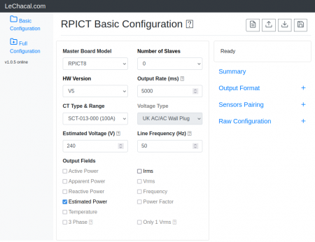
You can now edit the configuration. | |||
[[File:Screenshot_2021-11-01_20-22-56.png | 450px | link=http://lechacal.com/RPICT/config/generator/latest/index.html]] | |||
==Data Output== | |||
Using the manufacture firmware the data output is: | |||
NodeID P1 P2 P3 Irms1 Irms2 Irms3 Irms4 Vrms1 Vrms2 Vrms3 T | |||
P1 is Real Power 1 from CT1/V1 | |||
Irms is the rms current on CT1 | |||
Vrms is the rms voltage | |||
T is the DS18B20 temperature. All additional DS18B20 will follow. | |||
Real Powers are computed using the following rules: | |||
RealPower1 -> CT1 & V1<br> | |||
RealPower2 -> CT2 & V2<br> | |||
RealPower3 -> CT3 & V3<br> | |||
Irms4 -> CT4<br> | |||
These rules can be modified in the configuration. | |||
Other output type can be streamed out. This should be configured in the unit. | |||
All outputs type available are | |||
* Vrms (V) | |||
* Irms (A) | |||
* Real Power (W) | |||
* Apparent Power (W) | |||
* Power Factor | |||
* Estimated Power | |||
* RTD Temperature | |||
* DS18B20 Temperature | |||
==Restore Default Config== | |||
You should have received a key when acquiring the unit. Use this key to download and restore the default configuration.<br> | |||
If the key was XXXX then execute these commands below. Replace XXXX with your own key. | |||
$ wget lechacal.com/hardware/c/XXXX.conf | |||
$ lcl-rpict-config.py -w XXXX.conf | |||
=Simple Python Example= | |||
To work with the default configuration we have created a simple python program as demonstration. We invite you to look at the code. | |||
To get the program and run it do the following commands: | |||
wget lechacal.com/RPICT/example/RPIZ_CT4V3T2_DEMO_01.py.zip | |||
unzip RPIZ_CT4V3T2_DEMO_01.py.zip | |||
python RPIZ_CT4V3T2_DEMO_01.py | |||
The output will look like this below. | |||
[[File:Screenshot_2020-05-24_14-45-07.png |400px]] | |||
=Mezzanine Boards= | =Mezzanine Boards= | ||
| Line 97: | Line 164: | ||
This is a basic board extending all unused I/O pins of the Arduino microcontroller. These are presented as male pin header. Ground and 5V are also available for each pin. | This is a basic board extending all unused I/O pins of the Arduino microcontroller. These are presented as male pin header. Ground and 5V are also available for each pin. | ||
This will only be used if you are planning to write your own firmware. | |||
Each available pins are listed below. | |||
{| class="wikitable" | {| class="wikitable" | ||
| Line 131: | Line 202: | ||
| ADC6 | | ADC6 | ||
| A6 | | A6 | ||
| | | - | ||
|- | |- | ||
| ADC7 | | ADC7 | ||
| A7 | | A7 | ||
| | | - | ||
|- | |- | ||
| | | PD7* | ||
| | | - | ||
| | | D7 | ||
|- | |- | ||
| | | PD6* | ||
| | | - | ||
| | | D6 | ||
|- | |- | ||
|}[[File:IMG_0070.jpeg | 300px]] | |} | ||
* The PCB might have PD2 and PD3 marking which is incorrect. | |||
[[File:IMG_0070.jpeg | 300px]] | |||
===CT8 Mezzanine=== | ===CT8 Mezzanine=== | ||
| Line 156: | Line 230: | ||
Enclosure kit is available in [http://lechacalshop.com/gb/internetofthing/40-enclosure-kit-for-rpizct4v3t1.html the shop]. | Enclosure kit is available in [http://lechacalshop.com/gb/internetofthing/40-enclosure-kit-for-rpizct4v3t1.html the shop]. | ||
[[File: | [[File:IMG_0096_small.png | 300px]][[File:IMG_0095_small.png | 300px]] | ||
=Files= | =Files= | ||
| Line 163: | Line 237: | ||
[http://lechacal.com/RPICT/ZCT4V3T1/ | [http://lechacal.com/RPICT/ZCT4V3T1/RPIZ_CT4V3T2_v1.0.ino Default RPIZ_CT4V3T2 Sketch V1.0.0]. --> For hardware version 1.3 only | ||
[http://lechacal.com/RPICT/ZCT4V3T1/RPIZ_CT4V3T2_v1.2.ino Default RPIZ_CT4V3T2 Sketch V1.2.0]. --> For hardware version 1.4 | |||
[http://lechacal.com/RPICT/ZCT4V3T1/RPIZ_CT4V3T2_v1.3.ino Default RPIZ_CT4V3T2 Sketch V1.3.0]. --> For hardware version 1.4 | |||
[http://lechacal.com/RPICT/sketch/RPIZ_CT4V3T2_v4.0.2_r00.ino RPIZ_CT4V3T2_v4.0.2_r00.ino][http://lechacal.com/RPICT/sketch/RPIZ_CT4V3T2_v4.0.2_r00.ino.hex hex] --> For hardware version 1.5 | |||
[http://lechacal.com/RPICT/sketch/RPICT_MCP3208_v4.2.0_TEMP08.ino RPICT_MCP3208_v4.2.0_TEMP08.ino][http://lechacal.com/RPICT/sketch/RPICT_MCP3208_v4.2.0_TEMP08.ino.hex hex] --> For hardware version 1.5 | |||
==Programming== | ==Programming== | ||
| Line 169: | Line 251: | ||
The RPIZ_CT4V3T2 can be programmed using the [[NanoProg_v1 | NanoProg]]. | The RPIZ_CT4V3T2 can be programmed using the [[NanoProg_v1 | NanoProg]]. | ||
'''IMPORTANT''' | '''IMPORTANT'''-> Make sure the Raspberrypi Zero is removed before connecting the NanoProg. | ||
Connect the Nanoprog with the RPIZ_CT4V3T2 unit using the 6pin ribbon cable. Make sure grounds are connected together. | |||
Use '''Tools | Board | Arduino Uno'''. | |||
Upload sketch using '''Sketch''' | '''Upload Using Programmer'''. | |||
Once the Arduino firmware flashed the default config must be loaded using the lcl-rpict-config.py tool. | Once the Arduino firmware flashed the default config must be loaded using the lcl-rpict-config.py tool. | ||
[[File:IMG_1888_small.png | 300px]] | [[File:IMG_1888_small.png | 300px]] | ||
Latest revision as of 10:09, 11 October 2023


Overview
The RPIZCT4V3T2 can be configured to read both single phase and 3 phase systems.
Several temperature sensors can be interfaced. It has support for both DS18B20 temperature sensor and RTD thermocouples.
It is designed to host a user provided Raspberrypi zero.
The main PCB has provision for one extra mezzanine card to extend the number of sensors.
An enclosure solution is proposed using aluminium extruded case.
RTD MODULES ARE NO LONGER SOLD - The board will be provided without RTD support. We have dropped the development for these.
Specifications
cpu
- Hosts RaspberryPi Zero
- ATmega328 mcu (Arduino UNO)
Sensors
- 4 CT sensors
- 3 AC Voltage
- 1 DS18B20 port (temperature)
- 1 RTD Thermocouple port
Power
- Powered from Raspberrypi (microusb)
Other
- Fits in Aluminium Enclosure from Evatron
- Option to stack mezzanine board for additional sensors.
Recommended sensors
- AC Current sensor:
- SCT-013-000
- SCT-019
- SCT-006
- AC Voltage sensor:
- UK: 77DB-06-09
- EU: 77DE-06-09
- US: 77DA-10-09
- ZMPT101B
- Temperature:
- DS18B20
- Temperature RTD:
- PT100
- PT1000 (modification required)
Temperature Sensor
DS18B20
The temperature port supports mutiple sensor on the same Onewire line.
The sketch is programmed to search for all connected probe at bootup and output all their values when polled.
Multiple probes should connected as shown below.

When a new probe is connected the arduino mcu must be restarted for the new probe to be registered. You can reset the Arduino chip with the command below:
lcl-rpict-config.py -a
To connect multiple probe together we suggest the use of our DS18B20 junction board.
RTD Thermocouple
A MAX31865 RTD module is used to interface the RTD sensor with the arduino controller.
There is support for 2 3 and 4 wires thermocouples. Also both PT100 and PT1000 can be used.
Units are sold by default setup for 3 wires PT100 units. Other setup can be configured and require some basic soldering. Full details to configure the MAX31865 module are given by ADafruit webpage here.
https://learn.adafruit.com/adafruit-max31865-rtd-pt100-amplifier/rtd-wiring-config

Software Configuration
For any units ordered before the 1st of February 2022 the firmware version is version 3. Follow this link below for configuration. If possible upgrade to firmware version 4.
Before 1st Feb 22 RPIZ_CT4V3T1 Configuration
Upgrading to sketch version 4
First make sure the lcl-package is installed if not done already.
wget lechacal.com/RPICT/tools/lcl-rpict-package_latest.deb
sudo dpkg -i lcl-rpict-package_latest.deb
Now starts a server instance on the Raspberrypi using.
lcl-server.sh
You can now access the Raspberrypi configuration server if you point your browser to the link below
http://raspberrypi:8000/
You can now edit the configuration.
Data Output
Using the manufacture firmware the data output is:
NodeID P1 P2 P3 Irms1 Irms2 Irms3 Irms4 Vrms1 Vrms2 Vrms3 T
P1 is Real Power 1 from CT1/V1 Irms is the rms current on CT1 Vrms is the rms voltage T is the DS18B20 temperature. All additional DS18B20 will follow.
Real Powers are computed using the following rules:
RealPower1 -> CT1 & V1
RealPower2 -> CT2 & V2
RealPower3 -> CT3 & V3
Irms4 -> CT4
These rules can be modified in the configuration.
Other output type can be streamed out. This should be configured in the unit.
All outputs type available are
- Vrms (V)
- Irms (A)
- Real Power (W)
- Apparent Power (W)
- Power Factor
- Estimated Power
- RTD Temperature
- DS18B20 Temperature
Restore Default Config
You should have received a key when acquiring the unit. Use this key to download and restore the default configuration.
If the key was XXXX then execute these commands below. Replace XXXX with your own key.
$ wget lechacal.com/hardware/c/XXXX.conf
$ lcl-rpict-config.py -w XXXX.conf
Simple Python Example
To work with the default configuration we have created a simple python program as demonstration. We invite you to look at the code.
To get the program and run it do the following commands:
wget lechacal.com/RPICT/example/RPIZ_CT4V3T2_DEMO_01.py.zip
unzip RPIZ_CT4V3T2_DEMO_01.py.zip
python RPIZ_CT4V3T2_DEMO_01.py
The output will look like this below.

Mezzanine Boards
RPIZ_CT4V3T2 has provision to stack an extra mezzanine board to extend the number of sensors. We currently have 2 type of mezzanine.
Generic Mezzanine
This is a basic board extending all unused I/O pins of the Arduino microcontroller. These are presented as male pin header. Ground and 5V are also available for each pin.
This will only be used if you are planning to write your own firmware.
Each available pins are listed below.
| Atmel Pin | Arduino Analog | Arduino Digital |
|---|---|---|
| PC0 | A0 | D14 |
| PC1 | A1 | D15 |
| PC2 | A2 | D16 |
| PC3 | A3 | D17 |
| PC4 | A4 | D18 |
| PC5 | A5 | D19 |
| ADC6 | A6 | - |
| ADC7 | A7 | - |
| PD7* | - | D7 |
| PD6* | - | D6 |
- The PCB might have PD2 and PD3 marking which is incorrect.

CT8 Mezzanine
The CT8 mezzanine offers an extra 8 CT connection with a 12 bit ADC. Increasing the total number of CT to 12.
Enclosure
The board has been designed to fit inside an aluminium extruded enclosure. 3D printed end plates are provided. Enclosure kit is available in the shop.


Files
Arduino Sketch
Default RPIZ_CT4V3T2 Sketch V1.0.0. --> For hardware version 1.3 only
Default RPIZ_CT4V3T2 Sketch V1.2.0. --> For hardware version 1.4
Default RPIZ_CT4V3T2 Sketch V1.3.0. --> For hardware version 1.4
RPIZ_CT4V3T2_v4.0.2_r00.inohex --> For hardware version 1.5
RPICT_MCP3208_v4.2.0_TEMP08.inohex --> For hardware version 1.5
Programming
The RPIZ_CT4V3T2 can be programmed using the NanoProg.
IMPORTANT-> Make sure the Raspberrypi Zero is removed before connecting the NanoProg.
Connect the Nanoprog with the RPIZ_CT4V3T2 unit using the 6pin ribbon cable. Make sure grounds are connected together.
Use Tools | Board | Arduino Uno.
Upload sketch using Sketch | Upload Using Programmer.
Once the Arduino firmware flashed the default config must be loaded using the lcl-rpict-config.py tool.
