RPICT Stacking Version 5
This page is for version 5 units. For older versions please refer to this page here.
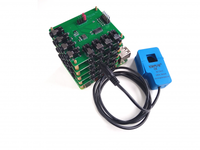
RPICT7V1 RPICT4V3 and RPICT8 version 5 boards can be stacked with an additional slave board. Up to 4 slaves can be stacked on top of a master board. Increasing the number of CT capacity to up to 40.
Version 3 users. Read this -> Version 5 stacking differ from version 3. One individual board can no longer be converted from master to slave or slave to master. Each board is setup as master or slave by design.
Stacking offers the ability to compute Current/Voltage pairs between different board type. For example one might stack 1 RPICT7V1 with 1 RPICT8 and compute Active Power against V1 on RPICT7V1 and all other 15 CT channels on both RPICT7V1 and RPICT8.
RPICT board Stacking
The rpict board concerned by this topic are
RPICT7V1 Slave have not been created and might never be. Use a RPICT4V3 if you need multiple voltage input.

Software Limitations
Firmware 3
The default sketch limits the number of CV pairs to 28. This allows 3 slave units to be stacked on top of the master board.
If a 4 slaves stack is required upgrade to Firmware 4 and use hardcoded configuration. See below.
If you want to upgrade to firmware 4 follow this. Upgrading to sketch version 4.
Firmware 4
Using the normal configuration with the web tool there is support for up to 3 slaves stacked on top of the master board.
Exception made to a stack of one RPICT8 master and 4 RPICT8 slaves which can be configured from the web tool without any limitations.
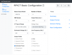
To find out what configuration is possible just go to the configuration tool below in the basic mode and try various configuration with various slave number. Limited options will be grayed out.
http://lechacal.com/RPICT/config/generator/v1.0.3/index.html
If 4 slaves is a requirement we recommend the use of the hardcoded configuration. See the 'hardcoded configuration' section in the full configuration below.
http://lechacal.com/RPICT/config/generator/v1.0.3/advanced_configuration.html
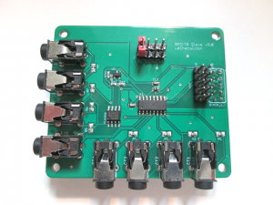
Slave Board Setup
There are two types of slave boards which are the RPICT8 Slave and RPICT4V3 Slave.
At purchase time there are two options for slave board to be chosen from. Slave 1&3 and Slave 2&4. The main difference between the 2 is the position of the stacking connector.
Slave 1&3
Slave 1&3 can only be stacked on a the master board or a Slave 2&4.
A typical 2 board setup would involve one master and a slave 1&3.
Slave 2&4
Slave 2&4 can only be stacked on top of a Slave 1&3.

Jumper Setup
The ID of the slave board is selected by means of a jumper link. There are 4 possible slave ID possible. 1 2 3 or 4. See S1 S2 S3 S4 marking on the PCB.
Software Configuration
The RPICT boards do not configure automatically after being stacked. The user must configure this using the tools provided.
The master board can be configured over serial port.
Firmware 3
The documentation for serial configuration can be found on this page.
[Over Serial Configuration - Sketch 3.0]

Starting from sketch 2.4 the board can be configured with the online configurator.
Firmware 4
The documentation for serial configuration can be found on this page. Over_Serial_Configuration_-_Sketch_4
Starting from sketch 4 the board can be configured with the online configurator.
If you want to upgrade to firmware 4 follow this. Upgrading to sketch version 4.
Recently purchased units are already using firmware 4.
Optimisation
Cycle scanning time might get rather large when using high stacks. It might be a good idea to reduce the Ncycle parameter to a lower number than the default of 20 cycles. 5 cycles usually works well but even as low as 2 might also work too.
Ncycle = 5
Frequently Asked
1 - How do I access the slave data? The data from the slave will be shown on the same serial output as when used as master only. The user must configure with the tools shown above the output for the slave.
2 - Can I compute power using voltage on the master and current on a slave? Yes. The configuration is designed specifically for this purpose.
3 - Are performances lower when computing power with sensors on different levels? Absolutely none. Performances are exactly the same.
4 - Can I mix 3 phase and single phase computation in one configuration? This is only possible with Firmware 4.
5 - Can I assign each single phase of a 3 phase system over different levels? Yes. Entirely possible. One of our basic default configuration actually does that.