RPI LCT8: Difference between revisions
No edit summary |
No edit summary |
||
| Line 7: | Line 7: | ||
This page is for board specific information. More information can be found on the [[Raspberrypi_Current_and_Temperature_Sensor_Adaptor | generic page for RPICT series]]. | This page is for board specific information. More information can be found on the [[Raspberrypi_Current_and_Temperature_Sensor_Adaptor | generic page for RPICT series]]. | ||
The RPI | The RPI LCT8 has been specifically designed for large CT of 400A and more. CT connector are screw terminal types as opposed to jack connectors. | ||
* | * 8 AC current sensor | ||
* Fit on Raspberrypi 4 holes mounting pattern. | * Fit on Raspberrypi 4 holes mounting pattern. | ||
* ATmega328 Mcu. | * ATmega328 Mcu. | ||
| Line 41: | Line 39: | ||
==Recommended sensors== | ==Recommended sensors== | ||
===AC Current sensor=== | ===AC Current sensor=== | ||
| Line 49: | Line 46: | ||
Enquire with us for other CT. | Enquire with us for other CT. | ||
==Configuration== | ==Configuration== | ||
| Line 67: | Line 60: | ||
==Stacking== | ==Stacking== | ||
The | The RPI_LCT8 is not readily stackable. | ||
See this page below for an adaptation to stack 2 units. | See this page below for an adaptation to stack 2 units. | ||
| Line 131: | Line 124: | ||
[http://lechacal.com/RPICT/7CT1V/RPICT_MCP3208_v3.0.2.ino Default Sketch V3.0.2.]<br> | [http://lechacal.com/RPICT/7CT1V/RPICT_MCP3208_v3.0.2.ino Default Sketch V3.0.2.]<br> | ||
==Related Pages== | ==Related Pages== | ||
Revision as of 13:13, 8 April 2019

This page is for board specific information. More information can be found on the generic page for RPICT series.
The RPI LCT8 has been specifically designed for large CT of 400A and more. CT connector are screw terminal types as opposed to jack connectors.
- 8 AC current sensor
- Fit on Raspberrypi 4 holes mounting pattern.
- ATmega328 Mcu.
- Adapted for 400A CT.
Compatibility
| Version | Compatible? |
|---|---|
| Raspberrypi 1 A | Yes |
| Raspberrypi 1 B+ | Yes |
| Raspberrypi 2 B | Yes |
| Raspberrypi 3 B | Yes |
| Raspberrypi 3 B+ | Yes |
Recommended sensors
AC Current sensor
Most current output CT sensor with 5A secondary can be used. In particular
- SCT-024/5A
Enquire with us for other CT.
Configuration
See general instructions for configuration below:
Over Serial Configuration - Sketch 2.8
Over Serial Configuration - Sketch 3.0
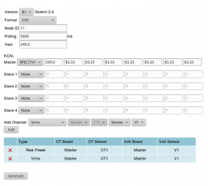 The board can be configured with the online configurator.
Stacking
The RPI_LCT8 is not readily stackable.
See this page below for an adaptation to stack 2 units.
RPI_LCT4V3 stack with RPI_LCT8 application example.
View the data with Python
Please note the configuration must have Emonhub format enabled (format=3). The example script below will be a good starting point.
First of all make sure you have python-serial package installed
$ sudo apt-get install python-serial
Then copy the following into an executable file and run it.
#!/usr/bin/python
import serial
ser = serial.Serial('/dev/ttyAMA0', 38400)

try:
       while 1:
               response = ser.readline()
               z = response.split(" ")
               if len(z)>=7:
                       print "Vrms 1: %s Volt" % z[1]
                       print "Vrms 2: %s Volt" % z[2]
                       print "Vrms 3: %s Volt" % z[3]
                       print "RealP 1: %s Watt" % z[4]
                       print "RealP 2: %s Watt" % z[5]
                       print "RealP 3: %s Watt" % z[6]
                       print "RealP 4: %s Watt" % z[7][:-2]
except KeyboardInterrupt:
       ser.close()
Emoncms Config (Emonhub)
For default configuration.
 [[11]]
   nodename = my_RPI_LCT4V3
   hardware = RPI_LCT4V3
   [[[rx]]]
      names = Vrms1, Vrms2, Vrms3, RP1, RP2, RP3, RP4
      datacode = 0
      scales = 1,1,1,1,1,1,1
      units = V,V,V,W,W,W,W
Using the default sketch the output will be
NodeID Vrms1 Vrms2 Vrms3 RealPower1 RealPower2 RealPower3 RealPower4
- RealPower in Watts
- Vrms in Volts

Files
Default Sketch
Default Sketch V3.0.0.
Default Sketch V3.0.1.
Default Sketch V3.0.2.
Related Pages
Calibration VCAL ICAL PHASECAL