RPICT7V1 v2.0
RPICT7V1 version 2.0
This page is for board specific information. More information can be found on the generic page for RPICT series.

This is the new version of the RPICT7V1. It now features the same microcontroller as an Arduino UNO. The best of all is the possibility to stack up to 5 boards together to increase the sensor capacity onto one single raspberrypi.
- 7 AC current sensors.
- 1 AC Voltage sensor.
- Compute real power.
- Fit on Raspberrypi 4 holes mounting pattern.
- AtMega328 Mcu (Arduino UNO)
- MCP3208 ADC
- Stackable (up to 5 boards together)

Recommended sensors
- AC Current sensor: SCT-013-000
- AC Voltage sensor:
- UK: 77DB-06-09
- EU: 77DE-06-09
- US: 77DA-10-09 STA-4190D
Stacking Configuration
5 boards can be stacked together to offer up to 35 SCT sensors capacity on one Raspberrypi.
In the stacked configuration only one board has a Microcontroller which is the Master board. For the slave board the microcontroller should be removed.
Hardware Configuration for slave
2 Steps to configure a single board or master board as slave:
1 - Remove the 28 pin microcontroller.
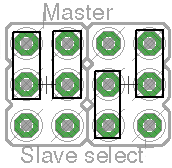
2 - Setup the jumper as shown below.
Always place the Master board at the bottom of the stack. The order of other boards above the master can be any.
Software Configuration
The master board can be configured over serial.
Using a serial line terminal program one can configure the following:
- Polling interval
- Output format (csv or emoncms)
- Calibration values (Voltage and Current)
- Voltage/current combinations for real power computation.
- Output channels
The documentation for serial configuration can be found on this page.
Over Serial Configuration - Sketch 2.1
Over Serial Configuration - Sketch 2.2
Over Serial Configuration - Sketch 2.3
Over Serial Configuration - Sketch 2.4
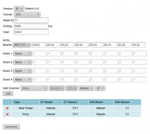 Starting from sketch 2.4 the board can be configured with the [online configurator].
Jumpers
There are four jumpers to configure the board as Master or Slave. The 5 possible configurations are:
| Type | Master | Slave 1 | Slave 2 | Slave 3 | Slave 4 |
|---|---|---|---|---|---|
| CS Pin | 10 | 6 | 7 | 8 | 9 |
| Jumpers | 
|

|

|
|

|
Files
(note boards are sold already flashed with latest firmware).
Emoncms Config
For default configuration. Used as single board only (not stacked).
 [[11]]
   nodename = my_RPICT7V1
   firmware = v1.2
   hardware = RPICT7V1
   [[[rx]]]
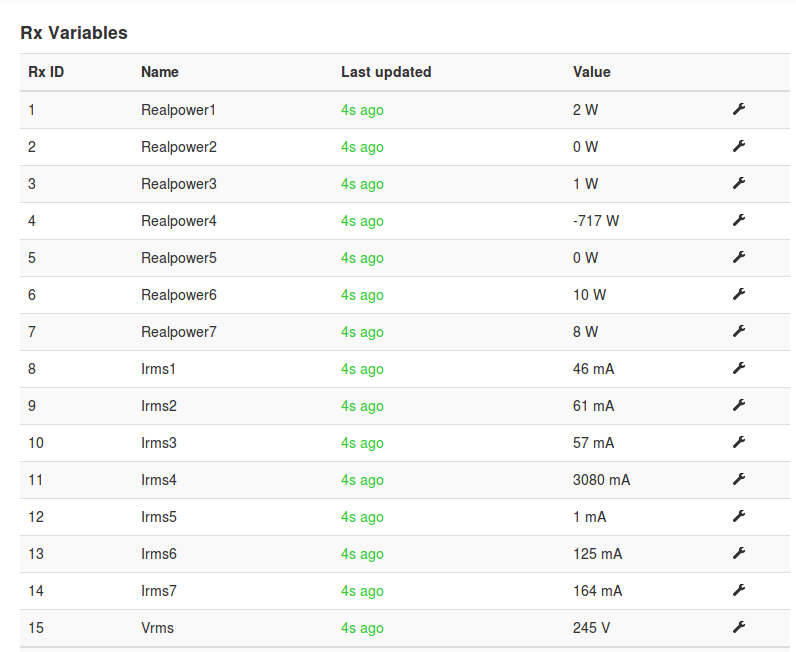
      names = Realpower1, Realpower2, Realpower3, Realpower4, Realpower5, Realpower6, Realpower7,Irms1, Irms2, Irms3, Irms4,Irms5,Irms6,Irms7,Vrms
      datacode = h
      scales = 1,1,1,1,1,1,1,1,1,1,1,1,1,1,1
      units =W,W,W,W,W,W,W,mA,mA,mA,mA,mA,mA,mA,V
Sketch Upload
Using Nanoprog
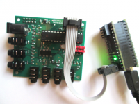
One can program the board using the Nanoprog programmer with a 6pin SPI connector.
In Arduino IDE select board as Arduino Uno. Upload sketch using File | Upload Using Programmer.
Using an ArduinoUNO
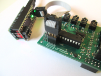
An Arduino UNO board can be used to program the chip. The micontroller should be removed from the RPICT7V1 board and fitted on the Uno to allow programming.


