RPICT4T4 Version 5: Difference between revisions
(→Files) |
|||
| (One intermediate revision by the same user not shown) | |||
| Line 38: | Line 38: | ||
|- | |- | ||
|Raspberrypi 4 B | |Raspberrypi 4 B | ||
|Yes | |||
|- | |||
|Raspberrypi 5 | |||
|Yes | |Yes | ||
|- | |- | ||
| Line 69: | Line 72: | ||
==Configuration== | ==Configuration== | ||
See general instructions for [[ | See general instructions for [[Over Serial Configuration - Sketch 3.0]]<br> | ||
==Default Data Output== | ==Default Data Output== | ||
Latest revision as of 12:50, 11 November 2023

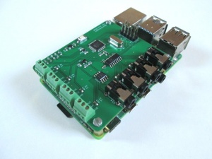
This page is for board specific information. More information can be found on the generic page for RPICT series.
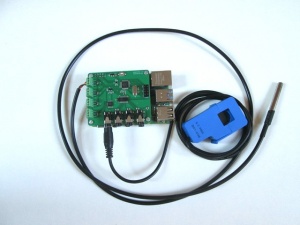
- 4x AC Current Sensors
- 4x DS18B20 Temperature Sensors
- DS18B20 extension possible to 32 probes.
- Microcontroller: Atmel atmega328p
- 12bit ADC
Compatibility

| Version | Compatible? |
|---|---|
| Raspberrypi 1 A | No |
| Raspberrypi 1 B | No mounting holes. |
| Raspberrypi 1 B+ | Yes |
| Raspberrypi 2 B | Yes |
| Raspberrypi 3 B | Yes |
| Raspberrypi 3 B+ | Yes |
| Raspberrypi 4 B | Yes |
| Raspberrypi 5 | Yes |
- Asus Tinkerboard has been reported to work with RPICT units. Note we wont be able to provide support for the Tinkerboard.
Current Sensor

Recommended sensor: SCT-013-000
For AC current only.
Temperature Sensor
Connector: 3.5mm Jack
The intended temperature sensor is the DS18B20.
The connector is a 3 way screw terminal connector.
Connection is as follow:
Vcc - Red
Din - Yellow
Gnd - Black
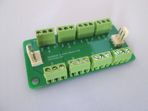
To extend the capacity from 4 to 32 probes the DS18B20 junction board should be used.
Configuration
See general instructions for Over Serial Configuration - Sketch 3.0
Default Data Output
Using the manufacture firmware the data output is:
NodeID P1 P2 P3 P4 T11 T12 T13 T14 T15 T16 T17 T28 T21 T22 T23 T24 T25 T26 T27 T28 T31 T32 T33 T34 T35 T36 T37 T38 T41 T42 T43 T44 T45 T46 T47 T48
Where: P1 P2 P3 P4 is estimated power in Watt. Txx temperature in Celsius. For example T23 is temperature probe 3 on port 2. If absent the channel will output a 'nan'
P1 being the estimated Power using CT1. `Estimated Power` computes power multiplying Irms by Vest. Where Vest is the estimated Voltage setup in the config. By default Vest=240V we recommend to change this to 220V or 110V if your local voltage supply differ.
If you prefer having current in Amperes rather than Estimated Power in Watt set VEST=1 in the configuration. In the same manner you can set VEST=1000 to get milliAmperes.
Restore Default Config
You should have received a key when acquiring the unit. Use this key to download and restore the default configuration.
If the key was XXXX then execute these commands below. Replace XXXX with your own key.
$ wget lechacal.com/hardware/c/XXXX.conf
$ lcl-rpict-config.py -w XXXX.conf
Emoncms Config (Emonhub)
For default configuration.
 [[11]]
   nodename = RPICT4T4
   hardware = RPICT4T4
   [[[rx]]]
       names = Power1, Power2, Power3, Power4, T11, T12, T13, T14, T15, T16, T17, T18, T21, T22, T23, T24, T25, T26, T27, T28, T31, T32, T33, T34, T35, T36, T37, T38, T41, T42, T43, T44, T45, T46, T47, T48
       datacode = 0
       scales = 1,1,1,1,1,1,1,1,1,1,1,1,1,1,1,1,1,1,1,1,1,1,1,1,1,1,1,1,1,1,1,1,1,1,1,1
       units = W,W,W,W,C,C,C,C,C,C,C,C,C,C,C,C,C,C,C,C,C,C,C,C,C,C,C,C,C,C,C,C,C,C,C,C
Python Example
Please note the uploaded sketch must have CSV enabled. The example script below will be a good starting point.
First of all make sure you have python-serial package installed
$ sudo apt-get install python-serial
Then copy the following into an executable file and run it.
 #!/usr/bin/python2
 import serial
 ser = serial.Serial('/dev/ttyAMA0', 38400)

 try:
        while 1:
             # Read one line from the serial buffer
             line = ser.readline()

             # Remove the trailing carriage return line feed
             line = line[:-2]

             # Create an array of the data
             Z = line.split(' ')

             # Print it nicely
             print ("----------")
             for i in range(len(Z)):
                 if i==0:
                     print ("NodeID: %s" % Z[0])
                 elif i in [1,2,3,4]:
                     print ("Power %d: %s W" % (i, Z[i]))
                 else:
                     print ("Temperature %d: %s C" % (i,Z[i]))

 except KeyboardInterrupt:
        ser.close()
Files
Unit are sold with the sketch below already loaded.

