RPICT7V1 Version 4: Difference between revisions
| (2 intermediate revisions by the same user not shown) | |||
| Line 1: | Line 1: | ||
[[File:IMG_1892_small.png | right | 400px]] | [[File:IMG_1892_small.png | right | 400px]] | ||
RPICT7V1 | RPICT7V1 Version 4 | ||
[http://lechacalshop.com/gb/internetofthing/65-rpict7v1version4.html | [[File:Link_to_the_shop.png | link=http://lechacalshop.com/gb/internetofthing/65-rpict7v1version4.html ]] | ||
This page is for board specific information. More information can be found on the [[Raspberrypi_Current_and_Temperature_Sensor_Adaptor | generic page for RPICT series]]. | This page is for board specific information. More information can be found on the [[Raspberrypi_Current_and_Temperature_Sensor_Adaptor | generic page for RPICT series]]. | ||
| Line 43: | Line 43: | ||
|- | |- | ||
|Raspberrypi 4 B | |Raspberrypi 4 B | ||
|Yes | |||
|- | |||
|Raspberrypi 5 | |||
|Yes | |Yes | ||
|- | |- | ||
Latest revision as of 12:50, 11 November 2023

RPICT7V1 Version 4
This page is for board specific information. More information can be found on the generic page for RPICT series.
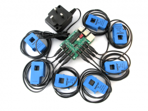
The RPICT7V1 version 4 differ from version 3 & 5 on the implementation of top end instrumentation amplifiers instead of just a burden resistor. This allow to have an optimum burden resistor and more flexibility on the measured range. Additionally Version 4 is able to support voltage output CT which version 3 & 5 can not.
- 7 AC current sensors.
- 1 AC Voltage sensor.
- Measure RMS Current and Voltage, Active power, Apparent Power, Power Factor, Reactive Power.
- Fit on Raspberrypi 4 holes mounting pattern.
- AtMega328 Mcu (Arduino UNO)
- MCP3208 12bit ADC
- High precision Instrumentation Amplifier AD623.
- Supports both Current or Voltage output CT.
Compatibility
| Version | Compatible? |
|---|---|
| Raspberrypi 1 A | No |
| Raspberrypi 1 B+ | Yes |
| Raspberrypi 2 B | Yes |
| Raspberrypi 3 B | Yes |
| Raspberrypi 3 B+ | Yes |
| Raspberrypi 4 B | Yes |
| Raspberrypi 5 | Yes |
- Asus Tinkerboard has been reported to work with RPICT units. Note we wont be able to provide support for the Tinkerboard.
Recommended Sensors

AC Current
Both current and voltage output are supported. Select between current or voltage CT support is made at purchase time.
- Current Output CT
- SCT-013-000 100A/50mA
- SCT-019 200A/33mA
- SCT-006 20A/25mA
- SCT-024 400A/100mA
- SCT-031 600A/100mA
- Voltage Output CT
- SCT-013-005
- SCT-013-010
- SCT-013-015
- SCT-013-020
- SCT-013-025
- SCT-013-030
- SCT-013-050
- SCT-013-060
Other CT sensor than the one listed here can be supported too. Contact us to enquire.
For Current output CT the RPICT board will have a burden resistor fitted.
For Voltage output CT there will be no burden resistor installed as this is already set inside the CT itself. The pro for this is the ability for the user to be able to change CT using the same RPICT7V1 Version 4 unit. Only the calibration coefficient has to be modified in the configuration. In the case of CT SCT-013-0XX the calibration coefficient equates to the last 2 digits divided by 1.5. e.g. SCT-013-030 ICAL is 30/1.5=20.
AC Voltage sensor
- UK: 77DB-06-09
- EU: 77DE-06-09
- US: 77DA-10-09
- ZMPT101B
Amplification Level
The new feature about RPICT7V1 Version 4 is the addition of instrumentation amplifiers AD623. This brings very sensitive and accurate method to measure physical values. Outstanding stability of the results has also been noticed.
Moreover the amplification level allows for more flexibility on the choice of the burden resistor. The scale is no longer depending on it. Hence improving on the linearity of the CT output for low current readings.
Read the following page to find out how resistors are calculated.
Amplification RPICT7V1 Version 4
Stacking Configuration
Version 4 can not be stacked at this stage. Contact us for enquiries on stacking development.
Software Configuration
Using a serial line terminal program one can configure the following:
- Polling interval
- Output format (csv or emonhub)
- Calibration values (Voltage and Current)
- Voltage/current combinations for real power computation.
- Output channels
The documentation for serial configuration can be found on this page.
Over Serial Configuration - Sketch 3.0
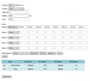
 The board can be configured with the online configurator.
Files
Default Sketch
Data Output
Using the manufacture firmware the data output is:
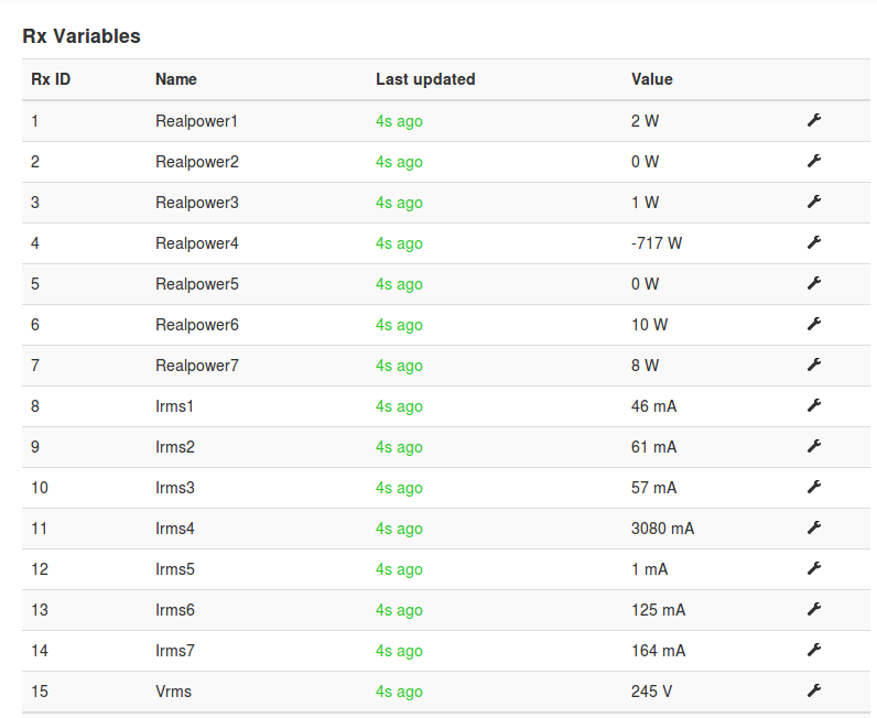
NodeID RP1 RP2 RP3 RP4 RP5 RP6 RP7 Irms1 Irms2 Irms3 Irms4 Irms5 Irms6 Irms7 Vrms
RP1 is Real Power 1 from CT1 Irms is the rms current on CT1 Vrms is the rms voltage
Real Powers are computed using the following rules:
RealPower1 -> CT1 & V1
RealPower2 -> CT2 & V1
... and so on.
These rules can be modified in the configuration if needed.
Other output type can be streamed out. This should be configured in the unit.
All outputs type available are
- Vrms (V)
- Irms (mA)
- Real Power (W)
- Apparent Power (W)
- Power Factor
- Estimated Power
- Frequency
- Reactive Power
Note concerning nan's
Version 4 in particular will output nan when no sensor is connected. In the particular case of the RPICT7V1 you should ensure the voltage sensor is connected otherwise both the voltage reading and associated CT port will output nan.
Also the default configuration only output the voltage reading associated with CT1. Therefore you will find Vrms showing nan if CT1 is not connected.
Emoncms Config (Emonhub)
Make sure you read this first.
For default configuration. Used as single board only (not stacked).
 [[11]]
   nodename = my_RPICT7V1
   hardware = RPICT7V1
   [[[rx]]]
      names = RP1, RP2, RP3, RP4, RP5, RP6, RP7, Irms1, Irms2, Irms3, Irms4, Irms5, Irms6, Irms7, Vrms
      datacode = 0
      scales = 1,1,1,1,1,1,1,1,1,1,1,1,1,1,1
      units =W,W,W,W,W,W,W,mA,mA,mA,mA,mA,mA,mA,V
Related Pages
Howto setup Raspbian for serial read
How to calibrate the Voltage Port

