RPICT4V3 v2.0
RPICT4V3 Version 2

This page is for board specific information. More information can be found on the generic page for RPICT series.
- 8 AC current sensors.
- Compute real power.
- Fit on Raspberrypi 4 holes mounting pattern.
- AtMega328 Mcu (Arduino UNO)
- MCP3208 ADC
- Stackable (up to 5 boards together)
Compatibility
| Version | Compatible? |
|---|---|
| Raspberrypi 1 A | No |
| Raspberrypi 1 B+ | Yes |
| Raspberrypi 2 B | Yes |
| Raspberrypi 3 B | Yes |
| Raspberrypi 3 B+ | Yes |
| Raspberrypi 4 B | Yes |
- Asus Tinkerboard has been reported to work with RPICT units. Note we wont be able to provide support for the Tinkerboard.
Recommended sensors
- AC Current sensor: SCT-013-000
- AC Voltage sensor:
- UK: 77DB-06-09
- EU: 77DE-06-09
- US: 77DA-10-09

Stacking Configuration
General stacking information is described in the RPICT stacking page.
RPICT_Stacking
Software Configuration
Using a serial line terminal program one can configure the following:
- Polling interval
- Output format (csv or emoncms)
- Calibration values (Voltage and Current)
- Voltage/current combinations for real power computation.
- Output channels
The documentation for serial configuration can be found on this page.
Over Serial Configuration - Sketch 2.2
Over Serial Configuration - Sketch 2.3
Over Serial Configuration - Sketch 2.4
Over Serial Configuration - Sketch 2.5
Over Serial Configuration - Sketch 2.6
Over Serial Configuration - Sketch 2.8
Over Serial Configuration - Sketch 3.0
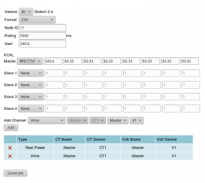 The board can be configured with the online configurator.

Files
Default Sketch
(note boards are sold already flashed with latest firmware).
noOSC Sketch
The Default sketch allows up to 28 computation nodes to be run. If more are needed for higher stacks then we recommend to use the noOSC sketch. This is the same as the default sketch but Over Serial Configuration (OSC) as been removed to allow up to 40 nodes to be computed. Configuration has to be edited in the sketch.
noOSC Sketch v1.0
noOSC Sketch v1.1

View the data with Python
Please note the configuration must have Emonhub format enabled (format=3). The example script below will be a good starting point.
First of all make sure you have python-serial package installed
$ sudo apt-get install python-serial
Then copy the following into an executable file and run it.
#!/usr/bin/python2
import serial
ser = serial.Serial('/dev/ttyAMA0', 38400)

try:
       while 1:
            # Read one line from the serial buffer
            line = ser.readline()

            # Remove the trailing carriage return line feed
            line = line[:-2]

            # Create an array of the data
            Z = line.split(' ')

            # Print it nicely
            if len(Z)>15:
                print ("----------")
                print ("          \tCT1\tCT2\tCT3")
                print ("RealPower:\t%s\t%s\t%s" % (Z[1], Z[6], Z[11]))
                print ("AppaPower:\t%s\t%s\t%s" % (Z[2], Z[7], Z[12]))
                print ("Irms     :\t%s\t%s\t%s" % (Z[3], Z[8], Z[13]))
                print ("Vrms     :\t%s\t%s\t%s" % (Z[4], Z[9], Z[14]))
                print ("PowerFact:\t%s\t%s\t%s" % (Z[5], Z[10], Z[15]))


except KeyboardInterrupt:
       ser.close()
To get the above example just enter the command below.
wget lechacal.com/RPICT/example/RPICT4V3_DEMO.py.zip
unzip RPICT3V1_DEMO_02.py.zip
and run it using
python RPICT4V3_DEMO.py
Emoncms Config (Emonhub)
Make you read this first.
For default configuration.
 [[11]]
   nodename = RPICT4V3
   hardware = RPICT4V3
   [[[rx]]]
       names = Vrms1,Vrms2,Vrms3,Realpower1,Realpower2,Realpower3,Realpower4
       datacode = 0
       scales = 1,1,1,1,1,1,1
       units = V,V,V,W,W,W,W

Related Pages
Howto_setup_Raspbian_for_serial_read