Raspberrypi Current and Temperature Sensor Adaptor: Difference between revisions
| Line 299: | Line 299: | ||
Emoncms is a very complete and user friendly interface. Using RPICT boards there are three possible options. | Emoncms is a very complete and user friendly interface. Using RPICT boards there are three possible options. | ||
The Emonhub option is now the standard setup. | |||
===Using Emonhub format=== | ===Using Emonhub format=== | ||
| Line 306: | Line 306: | ||
[[Use Emonhub with RPICT]] | [[Use Emonhub with RPICT]] | ||
===Using Emoncms installed on the Raspberrypi - Deprecated=== | |||
===Using Emoncms installed on the Raspberrypi=== | |||
The [https://github.com/emoncms/emoncms/blob/low-write/docs/setup.md Raspberripy OS distribution provided by OEM] for the Raspberry emonbase must be used for this purpose. In the Node section of emoncms the device with ID 11 will appear on its own. | The [https://github.com/emoncms/emoncms/blob/low-write/docs/setup.md Raspberripy OS distribution provided by OEM] for the Raspberry emonbase must be used for this purpose. In the Node section of emoncms the device with ID 11 will appear on its own. | ||
Revision as of 14:53, 22 February 2018

RPICT Series
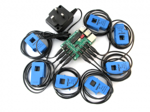
RPICT series are a set of Raspberrypi adaptor for current sensor (SCT) and temperature sensor. This page will introduce generalities concerning the RPICT series. Information for each individual board can be found below.
- RPICT3T1 - 3 CT 1 Temperature.
- RPICT3V1 - 3 CT 1 AC Voltage.
- RPICT4V3 - 4 CT 3 AC Voltage.
- RPICT4V3_v2.0 - 4 CT 3 AC Voltage.
- RPICT4T4 - 4 CT 4 Temperature.
- RPICT7V1_v2.0 - 7 CT 1 AC Voltage.
- RPICT8 - 8 CT.
| Model | #CT | #Volt* | #Temp | Stackable | Config over serial** | |
|---|---|---|---|---|---|---|
| RPICT3T1 | 3 | 0 | 1 | No | Yes | |
| RPICT3V1 | 3 | 1 | 0 | No | Yes | |
| RPICT4T4 | 4 | 0 | 4 | No | Yes | |
| RPICT4V3 v1 | 4 | 3 | 0 | No | No | |
| RPICT4V3_v2.0 | 4 | 3 | 0 | Yes | Yes | |
| RPICT7V1 v1 | 7 | 1 | 0 | No | No | |
| RPICT7V1_v2.0 | 7 | 1 | 0 | Yes | Yes | |
| RPICT8 | 8 | 0 | 0 | Yes | Yes |
\* AC Voltage
\** Configuration over serial - The board can be configured without the need of an avr programmer.
All RPICT board connect to the GPIO connector and provide data via serial interface. An Arduino programmable microcontroller (ATtiny84 or Atmega328) operates the board. Source code for the microcontroller is freely available and can be modified for adaptation.
There are several options for logging and viewing the data. Python or Emoncms or anything able to read a serial port.
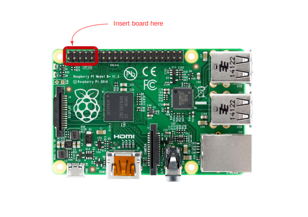
Insert on Raspberrypi
Note all RPICT series boards are compatible with all Raspberrypis.
Power is provided from the Raspberrypi. There is no need for extra power supply.
Current Sensor

Any current sensor with current output is compatible. Note there are considerations for the burden resistor which scales the range of measured current. We recommend the sensor below to start with.
Recommended sensor:
- SCT-013-000 50mA/100A
- SCT-019-000 33mA/200A
Connector: 3.5mm Jack
Measured range
The range is determined by the burden resistor fitted on the RPICT unit.
The default range is 100A on all RPICT series which correspond to a burden resistor of 24 Ohm. The table below shows alternative ranges with their associated burden resistor values.
| Sensor | Range (Rms Amps) |
Burden Resistor (Ohm) |
Calibration Coefficient (theoretical) |
|---|---|---|---|
| SCT-019-000 | 200 | 33 | 181.82 |
| SCT-013-000 | 100 | 24 | 83.33 |
| 60 | 39 | 51.28 | |
| 50 | 47 | 42.55 | |
| 30 | 75 | 26.67 | |
| 25 | 91 | 21.98 | |
| 20 | 120 | 16.67 | |
| 15 | 160 | 12.5 | |
| 10 | 240 | 8.333 | |
| 5 | 470 | 4.255 |
SCT-013-xxx other than SCT-013-000 are not supported. Likewise for any voltage output CT. Use the current output SCT with adequate burden resistor instead.
Notes
CT sensors only measures Alternative Currents (AC). Refer to sensor ACS715 for DC current.
Do not be tempted to use voltage output SCT sensor like SCT-013-030 or similar. All these SCT are SCT-013-000 with a burden resistor fitted inside them. However this is clearly not the best option as they are scaled for 1V output. Arduino microcontroller use 3.3V or 5V. We fit the burden resistor on the RPICT series for optimum scaling.
Temperature Sensor
Connector: 3.5mm Jack
The intended temperature sensor is the DS18B20 which can be configured in either parasite or normal mode.
Temperature sensors come with various connectors.
3.5mm Jack connector
The connection to a 3.5mm jack connector is shown below. This applies for board RPICT4T4. NOTE: Raspberrypi must be switched off while connecting and disconnecting the temperature sensor.
3 pin Molex
Bare wires
This applies for board RPICT3T1.
Voltage Sensor
An AC/AC adaptor is used to measure Voltage. We have a set of recommended adaptors:
- UK: 77DB-06-09
- EU: 77DE-06-09
- US: 77DA-10-09 or STA-4190D
The RPICT series are shipped using a basic calibration for the voltage port. A calibration would be needed if you feel the measured voltage is not accurate enough against another well trusted measuring device (scope, multimeter). Use this page to calibrate the voltage port.
To evaluate the power of an installation it is not strictly necessary to use the voltage sensor. Power can be estimated using an estimated fixed voltage (usually 240 or 110V). Voltage sensor becomes necessary if you wish to measure more accurately Real Power, Apparent Power and Power Factor. In addition the combination of a voltage sensor with a CT sensor will provide the direction of power (import/export).
Power Supply
The RPICT series do not need any extra PSU. The power from the Raspberrypi is used from the GPIO. Only the raspberrypi needs to be powered as normal.
View/Record data
Using plain Linux terminal
It is possible to read the data output directly from a linux terminal. i.e. reading the serial port.
Before hand you must ensure two things before getting this to work:
1/ The firmware of the board has been set to use output as CSV. Relevant sketch can be downloaded below. See OUTPUT_AS_CSV variable.
2/ The ttyAMA0 or ttyS0 serial on the raspberrypi is free. See Howto setup rpi3 for CSV reading.
As an example the output from the RPICT3T1 adaptor board will be in the format below. power in kw. temperature in deg celsius.
power1,power2,power3,temperature
Then on the Raspberrypi you can issue the commands
$ stty -F /dev/ttyAMA0 raw speed 38400
$ cat /dev/ttyAMA0
The terminal should then show something like this below
pi@raspberrypi ~ $ cat /dev/ttyAMA0
46,52,19.46
47,52,19.46
45,54,19.46
47,56,19.46
Why do I see a different output?
Plink is also an alternative we really like. Using plink
Using Python basic script
Using the same sketch as mentioned above a python script can be used to work with the data. The example script below will be a good starting point.
First of all make sure you have python-serial package installed
$ sudo apt-get install python-serial
Then copy the following into an executable file and run it.
#!/usr/bin/python
import serial
ser = serial.Serial('/dev/ttyAMA0', 38400)

try:
       while 1:
               response = ser.readline()
               z = response.split(",")
               if len(z)>=3:
                       print "Power 1: %s Watts" % z[0]
                       print "Power 2: %s Watts" % z[1]
                       print "Power 3: %s Watts" % z[2]
                       print "Temperature: %s Degrees" % z[3][:-2]
except KeyboardInterrupt:
       ser.close()
The above example is for the RPICT3T1 board. If using a different RPICT refer to the page of that particular board.
Using InfluxDB

InfluxDB is an open source project backed by Influxdata. It is all free if you install on your own server. Only a hosted solution is payable.
InfluxDB on its own is just a database ready to store the data and avail them. One then need a graphing package to view the data. Influxdata proposes Chronograf but Grafana can be used too.
We are giving a basic starting script here Example Using InfluxDB.
Using Emoncms
Emoncms is a very complete and user friendly interface. Using RPICT boards there are three possible options.
The Emonhub option is now the standard setup.
Using Emonhub format
This is only for newest units acquired after October 2017. This will be the format going forward.
Using Emoncms installed on the Raspberrypi - Deprecated
The Raspberripy OS distribution provided by OEM for the Raspberry emonbase must be used for this purpose. In the Node section of emoncms the device with ID 11 will appear on its own.
The RPICT board must output in the Emoncms specific format. Most RPICT can be configured manuallyto output in this format. This is the case for RPICT4T4, RPICT3V1, RPICT3T1, RPICT7V1 version 2 RPICT8, RPICT4V3 version 2. Others are only configured by flashing the microcontroller. These are RPICT7V1 version 1, RPICT4V3 version 1, RPICT3. Make sure you purchase the correct output for these one if you want to avoid reflashing the firmware.
With this solution the RPICT emulates a RFM12Bpi unit communication pattern. i.e. What will be sent to the Raspberrypi serial port will look as if it was sent by the RFM12Bpi.
Using CSV and forwarding the data
The CSV format can be used and forwarded to a remote Emoncms server. Typically emoncms.org. A script would be used for this purpose.
We are proposing a basic script template which can be installed as below.
wget lechacal.com/RPICT/tools/lcl-Emoncms-gateway.py.zip
unzip lcl-Emoncms-gateway.py.zip
wget lechacal.com/RPICT/tools/gateway.conf
Edit the gateway.conf file to reflect your own setting. Content will be self explanatory.
nano gateway.conf
Insert the RPICT and run
./lcl-Emoncms-gateway.py
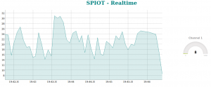
Using SPIOT

Download and install SPIOT on a given server. This could be the raspberrypi itself.
From the downloaded archive there is a directory called rpi containing python scripts and configuration file. Copy all these files on the raspberrypi (if not already there).
Make sure all .py files are executable:
$ chmod 755 *.py
Open the spiot.config file and modify the csv_forward section. port and hostname variable will be the most important ones for a first test. Keep apikey and node as they are to follow this example.
[csv_forward]
port = /dev/ttyAMA0
hostname = myserver/spiot
apikey = qbG31dQxFlG55mNM8G5ZTFkF0mrUbWg5
node = 20
baud = 38400
Then run the spiot_csv.py utility.
$./spiot_csv.py
Then point your webbrowser to the link below:
http://myserver/spiot/realtime.html?apikey=qbG31dQxFlG55mNM8G5ZTFkF0mrUbWg5&node=20&fields=f001
The last 5 minutes of the first channel will be shown on a graph.
Flashing the firmware / Upload Sketch
The onboard microcontroller can be re-programmed using the Arduino IDE software and an AVR programmer.
There is no need to reflash the microcontroller if you wish to change parameters for the following boards: RPICT7V1 version 2, RPICT4V3 version 2, RPICT8, RPICT3T1, RPICT3V1, RPICT4T4.
For other type of boards such as RPICT3, RPICT7V1 model 1, RPICT4V3 model 1 the only way to modify parameters is to modify the sketch and upload it to the microcontroller. This would applies for changing output format (csv/emoncms) or calibration values.
This link is a tutorial to upload Arduino sketches to the Attiny85.
Related Howto
How to program an Attiny85 or Attiny84

